

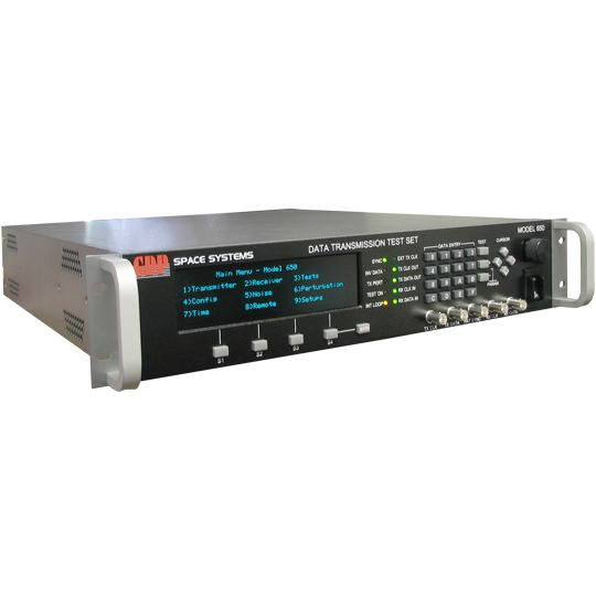
Model 650 Single Channel Data Transmission Test Set
- Data link test, analysis, and validation
- Comprehensive Bit Synchronizer Testing with internal noise source
- Independent Transmitter and Receiver
- IRIG Bit-coding, Convolutional Encoding and LDPC formats
The GDP Model 650 Data Transmission Test Set fills the need for high performance data-link verification and qualification at an affordable price. The user is provided with totally independent transmit and receive functions to allow rapid fault isolation and data link characterization. Simulated signal perturbations are created in the test lab by adding noise, baseline offset and varying signal levels. Features such as an internal 6-digit frequency synthesizer and IRIG Code generator and converter make the Model 650 especially suited to the test and evaluation of PCM Telemetry data link systems and components.
The Model 650 provides measurement capability for: Accumulated Bit Errors, Measured Bit Error Rate, Elapsed Test Time, Accumulated Errored Seconds, Errors per Second, Measured error Symmetry, Accumulated Bit Count Integrity loss (Bit Slips), Measured Transmit and Receive clock rate.
Operating ease and test flexibility is the result of using microprocessor control to augment high speed hardware functions. A high contrast vacuum fluorescent display provides setup and test result information in easy-to-use formats.
Functional Description
A modular architecture gives the Model 650 superior flexibility. A fully programmable frequency synthesizer allows transmit clock generation from 1 bps to 50 Mbps with 6-digit resolution. A flexible interface structure, which provides IRIG code converters for both input and output data, allows the Model 650 to fully support test and evaluation of telemetry receive, and processing systems.
The BER (Bit Error Rate) Module, is the major functional element in the Model 650. A microprocessor resident on the BER module controls the BERT transmit and receive circuits through user commands issued from the local front panel or remote control port. Communication between the microprocessor module and the BER module is accomplished using semaphores passed into a dual-port RAM architecture.
All high-speed functions are provided by hardware Functions such as data generation, PRN correlation, error detection and accumulation are performed by hardware. Low speed functions, such as test data accumulation and formatting for the front panel and remote monitoring ports, are provided by the embedded microprocessors.
User selectable Taps
or Dotting pattern
Selectable convolution order and polarity
Bits-in-Error
Seconds
Erred-Seconds
Slips
Symmetry
Average Bit-Error Rate
External Noise Input
Single Phase, 47-63 Hz
Optional