

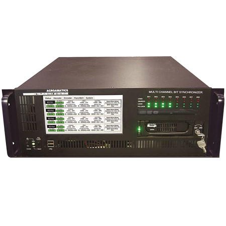
Model 2950AP Multi-Stream Bit Synchronizer
Data Quality and Signal Test:
- BERT/PRN BER Link Test Mode
- Frame Sync PCM BER Monitor
- Frame Lock/Loss Monitor
- Eb/No Signal Quality Output
- Viterbi Error Monitor Stats
Data Simulator/Generator
- Programmable rate, PRN Code, PCM Format and Code – to 40 Mbps
Bit Sync Status Monitors
- Front Panel LED Lock/Search/Loss
- On screen Performance Monitor
- Input Amplitude, Offset, Rate
- Deviation and Lock Status
Acroamatics’ Model 2950AP Multi-Stream Bit Synchronizer consists of up to sixteen 40 Mbps capable PCM Bit Synchronizers in a single 4U chassis. The Model 2950AP features a high intensity 8” LCD Touchscreen operator display & control panel as a standard feature, supporting both individual and group bit synchronizer parameter set-up, operation and status monitoring. Remote control of the unit is supported via Ethernet or serial remote interface, with Remote Control software provided to enable integrated remote set-up, control and monitoring of up to eight 8-stream Model 2950AP units from a single integrated remote operator interface. In addition, directly coupled LED status indicators provide precise bit sync lock and (with FSN option) live PCM frame sync lock status of each bit sync channel.
Each Model 2950AP bit sync is set-up, either individually or as a group, from the user-friendly GUI touchscreen operator interface. Storage for up to 20 system and individual channel set-ups is provided. Hot-swappable redundant power supplies assure rock solid system operation, while at the heart of the Model 2950AP Acroamatics’ newest generation of industry-leading bit synchronizer modules – our all new Model 1611P and 674DM Dual Stream PCM Bit Sync Mezzanine modules assure industry leading signal processing to assure the best possible lock and error performance under even the most trying difficult circumstances.
The Model 2950AP and its constituent internal 1611AP and 674DM bit sync module designs represent the first truly new “clean sheet” approach to modern bit sync design in a generation. Incorporation of the latest PGA based digital FIR filtering, digital phase locked-loop, NCO clock reconstruction, and digital amplitude and offset control design techniques are the underlying reasons for the astounding performance of our new Advanced Digital bit synchronizer. The Model 2950AP offers users programmable rates from 8 Hz to 40 Mbps using a huge variety of input and output code types and formats.
Standard PCM Sync Pattern/BERT test and monitoring, and Viterbi and QPSK encoder/decoder options assure state-of-the-art data format compatibility with the latest telemetry code and data formatting standards.
System Software
The Model 2950AP includes a distinctive and easily mastered operator interface accessed via its large high output front-panel LCD touchscreen display. Each of the high performance Bit Synchronizers installed within the system are controlled via its easy to follow GUI oriented, menu driven display panel. Clear and well labeled menu choices are provided, with distinctive status indicators and system setting choices. The 2950AP automatically recognizes its bit synchronizer hardware configuration, allowing upgrade and hardware changes without concern for hardware setting changes. Setup configurations are easily stored and retrieved, either as a group or individually. Remote users can control the unit via Ethernet port or serial interface with provided Acroamatics Remote Bit Sync Windows utility software. If two users are viewing the system simultaneously, both see the changes made in real-time by either user, in order to avoid errors.
SYSTEM FUNCTIONS
CHASSIS
SIGNAL INPUTS
SYNCHRONIZATION
Remote Control Software
Remote GUI Setup and Operation Status Windows software is provided with the Model 2950AP allowing remote network or serial remote unit operations. Multiple 2950AP units and other bit synchronizer products may be remotely operated using the provided software, such that up to 64 bit sync channels can be controlled by a single host computer.
DATA/CLOCK OUTPUTS
Specifications subject to change without notice.