

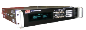
Model 2265EC PCM Bit Synchronizer / Encapsulator
- Up to 4-Channels per 2U Box
- 5 bps to 40 Mbps
- ENCAPSULATOR for a GDP Best Source Selector
- Loop Bandwidth Settings from 0.01% to 1.6%
- Extended LBW Range (Opt)
- Accepts NRZ-L/M/S, BiØ-L/M/S, DM-M/S; MDM-M/S
- Viterbi Decoder
- Frame Pattern Detector
- Signal/Data Quality Status
- Eb/No Measurement
- Frame Sync Pattern Error Rate (BER Status)
- Viterbi Error Rate
- BERT/ PRN BER Measurement
The GDP Model 2265EC Multi-Channel PCM Bit Synchronizer /Encapsulator houses up to 4 high performance bit synchronizer channels in a 2U chassis. The optimized digital design of this unit affords the highest performance characteristics currently available. This unit can be used as a stand-alone bit synchronizer and as a data Encapsulator for the GDP Diversity Combiner / Best Source Selector products.
The Model 2265EC is capable of maintaining synchronization with the signal of interest down to –3 dB Eb/No at signal levels as low as 100mVp -p. When searching for the signal, acquisition is attainable in less than 50 bits. The unit can maintain synchronization for a period of at least 256 bit periods without a transition.
The standard IRIG randomizer/derandomizer (others optionally available) for both forward and reverse sequences is provided. CCITT V.35 and V.36 scrambling/descrambling is also provided. A variety of Viterbi decoders are available including R1/2 K7 (Std), R3/4 K7 and R1/3 k7 (inquire for other FEC options).
To assure synchronization to the intended data stream, the Frame Pattern Detector may be invoked. Up to a 64 bit long pattern is detected. Maintaining synchronization with this pattern at the programmed repetition rate and synchronization strategy produces a lock signal. An Automatic Polarity Correction (APC) mode is provided for inverted data.
Each of the channels include three Analog inputs. Each channel provides outputs that include: TTL Coded PCM & TTL Encapsulated output. Each data output is associated with a coherent clock that is programmable to 0, 90, 180 and 270 degree.
The Encapsulator assembles reconstructed data and data quality information into a transfer frame (ENCAPSULATION). This transfer frame is suitable for passage by way of a data link to a GDP Best Source Selector. In this way the data quality information that is available at the first point of signal reception, is passed to a remote location where the Best Source Selector makes its decisions.
The MD2265EC includes several unique features to determine the quality of the data. The first is an Eb/No (Signal Quality) measurement. From this measurement the error rate of the data can be determined. The MD2265EC also determines BER from an embedded PCM frame synchronizer pattern, if present, as well as CER from the Viterbi stream when these modes are enabled. A bit-error-rate (BERT) function is also provided that allows link test in a short loop-back to verify proper operation of the module, or long loop-back to measure performance of the link. An advanced lock detector ensures a solid lock indication for the bit synchronizer.
The Auto Scan feature is available to scan the input for up to 8 combinations of bit rates, input codes, FEC and frame patterns (per Bit Sync). When one of the signals meets the programmed criteria, the Bit Sync automatically locks and recovers the data and clock.
Timing Input (Encapsulation): One (1) 1-pps (TTL)
Input Termination Selectable: 75Ω (50Ω Optional) or 10k Ω
Signal Amplitude: 0.1 Vp-p to 10 Vp-p not to exceed ±10 V
Tuning Resolution: X.XXXEN (1≤N≤7)
DC Offset: DC Offset + peak signal level not to exceed max. Signal Amplitude.
AC Offset: No degradation up to 100% of input signal at 0.1% of the bit rate.
Loop Bandwidth: 0.01% to 1.6% (Extended LBW Range Optional)
Acquisition Range: 2x LBW
Sync Acquisition Threshold: SNR 0 dB
Sync Maintenance: SNR –3 dB
Sync Acquisition: < 50 bits
Sync Retention: 256 bits without transitions
Bit Error Rate: < 1 dB to 40 Mbps
Randomizer/Derandomizer: IRIG 106 forward and reverse (Others Optional)
Descrambler: CCITT V.35/V.36
Viterbi Decoder: R 1/2, K 7 with G1/G2 Swap and G2 Invert, (others available)
Resequencer: QPSK/OQPSK/SOQPSK (Optional)
Frame Pattern Detector: Up to 64 bits with programmable strategy and APC
Auto Scan (Optional): Searches up to 8 Bit Rate, Code, Frame pattern, FEC sets per Bit Sync
Output Data Polarity: Input polarity normal / inverted.
Output Clock Phase: 0, 90, 180 & 270 degrees
BERT Function: Bit-Error-Rate PRN Generator/Error Detector (Option)
Encapsulation: Compatible with GDP Best Source Selector, up to 2-channels
RS422 (Each Channel) – Reconstructed Data & Clock; Encapsulated Data & Clock
Bipolar Tape Output (Each Channel) – 1 Vp-p – Coded PCM
BERT BER Measurement Results on Front Panel Display and Remote Control Port