

Model 2618P PCM Frame Validation System
- Removable USB Flash Drive Storage of System Configuration and Log Files
- Monitor up to 8 Independent PCM Streams
- Quick Visual Indication of Signal Quality
- Log File Creation with Data Export to Spreadsheet Applications
- Wizard Software assists with USB flash setup
Acroamatics’ Model 2618P PCM Frame Validation System can monitor as many as eight independent streams, providing a quick visual indication of the signal quality of your PCM data and verification that the received data corresponds to the expected frame characteristics.
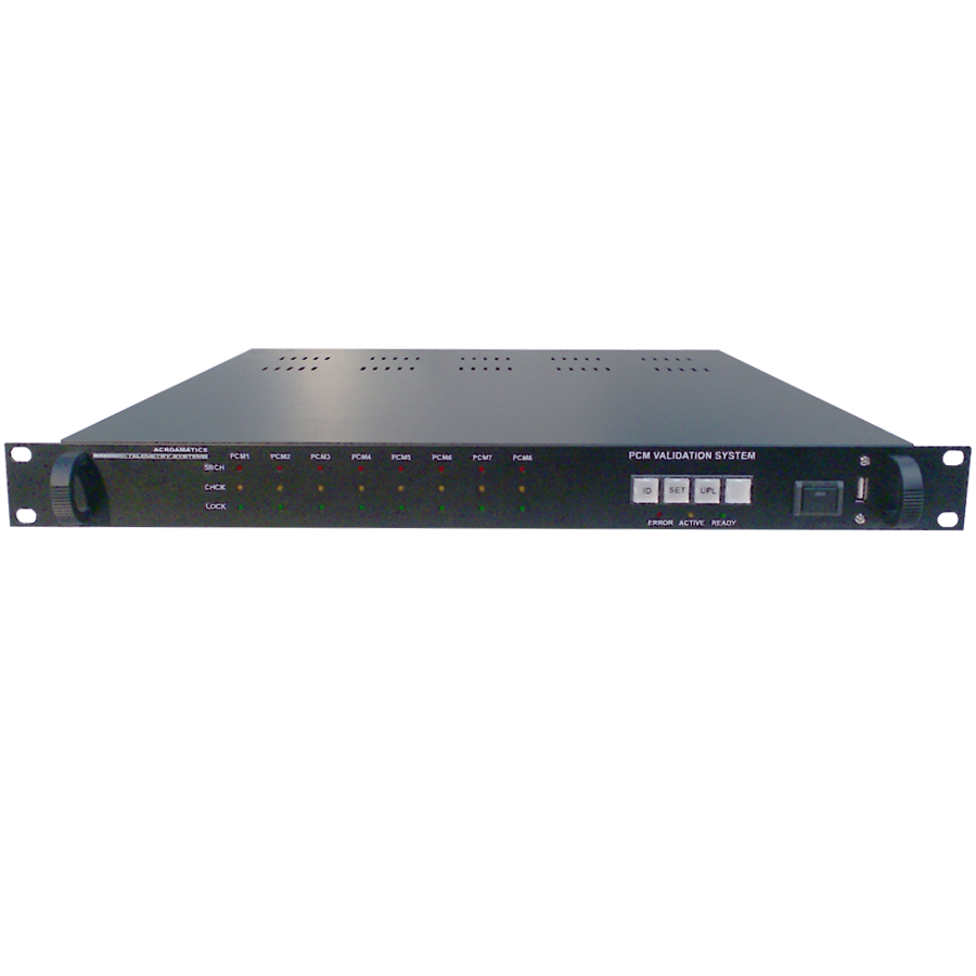
The 2618P accepts clock and data from PCM decryptors or Bit Synchronizers (up to eight) and bright LED indicators on the unit’s front panel indicate the data quality of each stream. At the same time, each stream is converted to a randomized NRZ signal for input to a downstream processor. A log file is also generated that records the system setup, plus time annotated frame status that can be imported into Excel or other applications for inclusion in mission reports.
Wizard software, which can be run on any Windows computer, guides you through the simple setup procedure to create or modify mission configurations. A USB flash drive transports the setup to the 2618P. Once the configuration is downloaded, the data monitoring and logging operation automatically starts, so virtually no additional operator action is required. At the end of a mission, a simple press of a button uploads the log file to a USB flash drive.
The 2618P is a 1U rack-mountable. It provides convenient front panel setup, data access and display of PCM stream status.
PHYSICAL
Specifications subject to change without notice.