

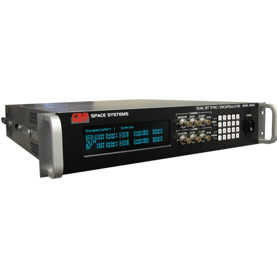
Model 2265 Single/Dual/Quad Bit Synchronizer
- The ‘Gold Standard’ Telemetry Bit Synchronizer
- Unbeaten performance in jitter and noise in worldwide side-by-side testing
- Superior Jitter Performance Unmatched in the Industry
- Better than 1db from theory all the way down to -3dB Eb/No
- Available in Single, Dual and Quad Channel Configurations
- Internal Frame Sync Pattern Detectors and Viterbi Decoders for each channel
The GDP Model 2265 Multi-Channel PCM Bit Synchronizer houses up to 4 high-performance bit synchronizer channels in a 2U chassis. The optimized digital design of this unit affords the highest performance characteristics currently available.
The Model 2265 is capable of maintaining synchronization with the signal of interest down to –3 dB Eb/No at signal levels down to 100mVpp. When searching for the signal, acquisition is attainable in less than 50 bits. The unit is very robust and can maintain synchronization for a period of at least 256 bit periods without a transition.
The standard IRIG randomizer/derandomizer for both forward and reverse sequences is provided. CCITT V.35 and V.36 scrambling/descrambling is also provided. A variety of Viterbi decoders are available including R1/2 K7 (Std), R3/4 K7 and R1/3 k7 (please inquire for other FEC options).
To assure synchronization to the intended data stream, the Frame Pattern Detector may be invoked. Up to a 64-bit long pattern is detected. Maintaining synchronization with this pattern at the programmed repetition rate and synchronization strategy produces a lock signal. An Automatic Polarity Correction (APC) mode is also provided for inverted data.
Each of the channels include four Analog inputs. Additional inputs are optionally available for RS-422 and TTL levels. Each channel also has a variety of outputs that include; three independent programmable TTL Coded PCM outputs and one TTL Auxiliary Coded output (4 total), two independently programmable (0, 90, 180 and 270 degree) TTL Clock outputs and one TTL Auxiliary Clock output (3 total), two RS-422 Coded PCM and two RS-422 Clock outputs. Front Panel Monitor BNCs are provided for each channel that include one Selected Input Monitor, one PCM Data Out and one Clock Out.
The MD2265 includes several unique features to determine the quality of the data. The first is an Eb/No (Signal Quality) measurement. From this measurement, the error rate of the data can be determined. The MD2265 also measured errors in the frame synchronizer pattern as well as errors in the Viterbi stream when these modes are enabled. A bit-error-rate (BERT) function is also provided. This allows link test in a short loop back to verify proper operation of the module, or long loop-back to measure performance of the link. An advanced lock detector ensures a solid lock indication for the module.
The Auto Scan feature is available to scan the input for up to 8 combinations of bit rates, input codes and frame patterns (per Bit Sync). When one of the signals is present, the Bit Sync automatically locks onto it and recovers the data and clock.
Bit Sync Lock, Eb/No, Bit Rate Deviation, Signal Presence, Signal Level, Bit Sync Lock-Loss-Count, and PRN BER/CER