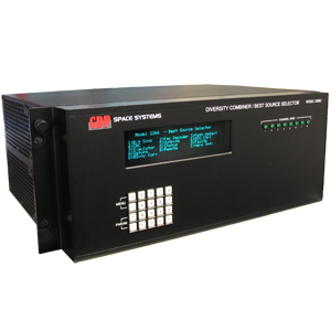
Model 2266C Multi-Channel PCM Bit Synchronizer Diversity Combining Best Source Selector

BEST SOURCE SELECTOR

  • Up to 8 channels per chassis
  • Up to 4 Independent BSS Groups
  • Works with encrypted data
  • Input stream correlated in time
  • Seamless stream switching on bit boundaries

MULTI-CHANNEL BIT SYNCHRONIZER

  • Up to 8 Channels
  • Performance within 1 dB of theory
  • Loop Bandwidth Settings from 0.01% to 1.6% (Extended LBWs available)
  • Accepts NRZ-L/M/S, BiØ-L/M/S, DMM/S; MDM-M/S

The GDP Model 2266C Multi-Channel PCM Bit Synchronizer/ Best Source Selector houses up to eight high-performance bit synchronizer channels. Each individual channel can be used as a normal Bit Sync and/or selected as a source for Best Source Selection. The optimized digital design of this unit affords the highest performance characteristics currently available. The unit operates to 40Mbps (20Mbps Standard, 40Mbps optional).

The standard IRIG randomizer/derandomizer for both forward and reverse sequences is provided. CCITT V.35 and V.36 scrambling/descrambling is also provided. A variety of Viterbi decoders are available including R1/2 K7 (standard). Please inquire for other FEC options (i.e. R3/4 K7, R1/3 K7 …). The unit can also be provided with an optional QPSK resequencing function that supports QPSK, OQPSK and SOQPSK data streams.

Best Source Selection of Non-Encrypted and Encrypted Data based on Signal Quality
The GDP Space Best Source Selector is an advanced, next generation implementation of best source selection based on signal/ data quality. Since signal quality is used in the decision making process, the unit does not need to see the synchronization pattern and the data can be encrypted. A digital data mode is also available for the case where receivers are located remotely and the analog signal is not available.

The unit can be divided into three major sections, Bit Synchronizer, Path Alignment, Path Selection. The Bit Synchronizers are providing data, clock, short-term data quality (signal quality of a small group of bits) and long-term data quality (signal quality over several hundred bits) to the Path Alignment and Path Selection sections. The Path Alignment section consists of correlators and path delay/advancement correction (works on encrypted streams). The Path Alignment section provides data, aligned in time, to the Path Selection section.

The Path Selection section uses the short-term and long-term data quality in addition to lock status to determine the best path. The unit provides the capability to switch data streams based on these quality measurements. Depending upon the number of valid sources, bit-by-bit output values are selected. This is accomplished by a Majority Voting technique weighted by signal quality. This automatic mode provides error correction that results in better then a 3.3dB performance improvement of the link.

SIGNAL INPUTS

Inputs per Channel (8 Ch. Max.)

Four (4) Analog or Digital [Other I/O configurations Available]
Input Impedance
Lo Z: 50 ohms (optional 75 ohm) or High Z (Selectable)
Levels
0.25 Vp-p to ± 12 Vp-p or RS-422 (Optional)
DC Offset
100% of the input peak-to-peak signal level.
AC Offset
No degradation up to 100% of input signal amplitude at 0.1% of the bit rate.
Input Codes
NRZ-L/M/S, BIØ-L/M/S, DM-M/S (std); MDM-M/S*
De-randomizer
RNRZ De-randomizer 2^9,11,15, 17, 20, 23 fwd and rev Normal / Inverted
Polarity
Normal / Inverted.
Viterbi Decoder
Constraint length 7, rate ½, G1 =171 octal G2= 133 octal G1/G2 Swap and G3 Invert (other viterbi options available)
Eb/No Measurement
-2 to +20 dB 0.5 dB resolution


SYNCHRONIZATION


Bit Rate Range
40 bps to 20 Mbps (40Mbps optional)
Tuning Resolution of Bit Rate
N(1≤N≤7)
Capture Range
Equal to LBW
Loop Bandwidths
0.01% to 1.6%
Sync Threshold
SNR –3 dB for NRZ, (-1 dB for BIØ) codes, square-sided data.
Sync Maintenance
SNR –3 dB with transition density 50%, LBW1 w/ NRZ-L
Sync Acquisition
50 bits or less
Sync Retention
256 bits without transitions, LBW1.
Bit Error Rate
Within 1 dB of theory over the full bit rate range
Frame Pattern Detector
Detection of up to 32 bits


OUTPUTS, EACH BIT SYNC CHANNEL


TTL (Each Channel)
Two Coded PCM and Two Clocks (Programmable 0, 90, 180, 270 degrees), plus one Selected Data & Clock Output for BSS Channels
RS422 (Each Channel)
Two Coded PCM and Two Clock (Programmable 0, 90, 180, 270 degrees), plus one Selected Data & Clock Output for BSS Channels
Bipolar Tape Output (Each Channel)
One +/-1V – Coded PCM
Lock Status
Bit Synchronization, Frame Pattern and Viterbi
Signal Quality Status
Eb/No, Deviation, Frame Sync Pattern Error Count, Viterbi Error Count and BERT / PRN BER Measurements on Front Panel Display and Remote Port