

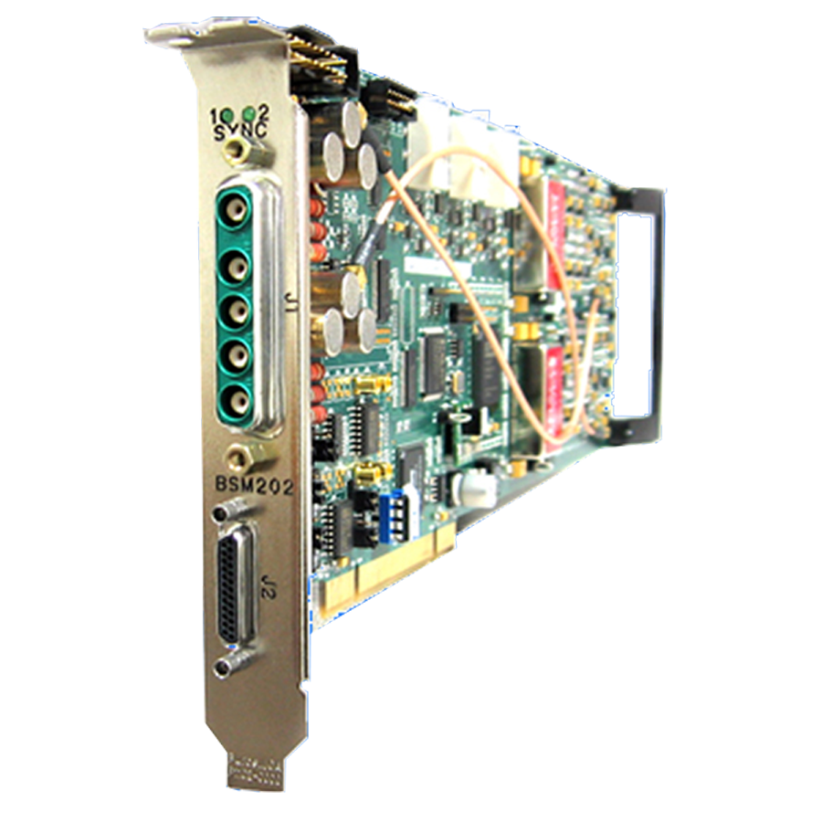
Model BSM202 Dual PCM Bit Synchronizer on PCI Card
- Dual Full Function PCM Bit Synchronizer on a single PCI Card (single channel
configurations also available) - Used in conjunctions with GDP’s Model 2365
- High-performance device designed to extract usable digital data from a noise contaminated signal environment
- Several unique features to determine the quality of the data:
- Eb/No (Signal Quality) measurement
- Measures errors in the frame synchronizer pattern/Viterbi stream when modes are enabled
- BERT function allows link tests to be performed using either a PRN-11 or PRN-15 data source
The GDP Model BSM202 is a Dual Channel PCM Bit Synchronizer on a single PCI card (single channel configurations also available). The BSM202 is a state-of-the-art high performance device that is designed to extract usable digital data from a noise contaminated signal environment. The optimized digital design of this unit affords the highest performance characteristics currently available.
The BSM202 is capable of maintaining synchronization with the signal of interest to Eb/No of -3 dB when the signal transition density is 50%. When searching for the signal, acquisition is attainable in less than 50 bits. The unit is very robust and can maintain synchronization for a period of at least 256 bit periods without a transition.
The standard IRIG randomizer/derandomizer for both forward and reverse sequences is provided. CCITT V.35 and V.36 scrambling/descrambling is also provided. A variety of Viterbi decoders are available including R1/2 K7 (Std), R3/4 K7 andR1/3 k7 (please inquire for other FEC options).
To assure synchronization to the intended data stream, the Frame Pattern Detector may be invoked. Up to a 64-bit long pattern is detected. Maintaining synchronization with this pattern at the programmed repetition rate and synchronization strategy produces a lock signal. An Automatic Polarity Correction (APC) mode is also provided for inverted data.
The BSM202 includes several unique features to determine the quality of the data. The first is an Eb/No (Signal Quality) measurement. From this measurement, the error rate of the data can be determined. The BSM202 also measured errors in the frame synchronizer pattern, as well as errors in the viterbi stream when these modes are enabled. A bit-error-rate (BERT) function is also provided. This allows link test in a short loop-back to verify proper operation of the module, or long loop-back to measure performance of the link. An advanced lock detector ensures a solid lock indication for the module.
The Auto Scan feature is available to scan the input for up to 8 combinations of bit rates, input codes and frame patterns (per Bit Sync). When one of the signals is present, the Bit Sync automatically locks onto it and recovers the data and clock.
RS422 or TTL